
A thermic fluid system is a small family of components — heater, pump, expansion tank, users, and pipe — but the design rules are unforgiving in specific places, because the failure modes are fluid death (lesson E3) and fire. This lesson walks the circuit in flow order, flags the three details that decide the system's fate, and closes with the safety architecture the fluid's combustibility demands.
The heater: film temperature, made in metal
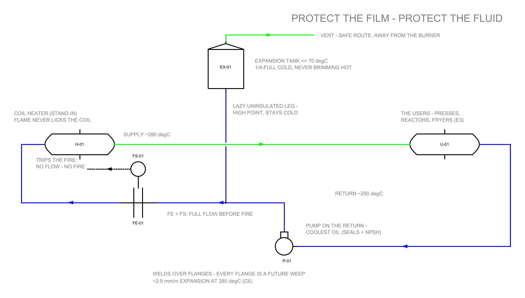
The standard Indian TF heater is a coil heater — one or more helical coils around a firebox, oil pumped through at deliberate velocity. Every design choice serves the film (lesson E3): burner geometry that heats by radiation and convection without flame licking the coil, oil velocity kept high (typically ~2 m/s and up in the radiant passes) so the film stays thin and cooled, and — the non-negotiable — full flow before fire: the burner permissive comes from proven oil flow (ΔP or flow switch), and low flow trips the fire before the film cooks. A TF heater is sized on heat duty like any boiler (lesson A10's arithmetic with cp ≈ 0.55), but it is protected on flow.
The expansion tank: the system's lungs — kept cold
Oil swells impressively with temperature — roughly 20–25% across a cold-to-300 °C start (thermic fluids expand about 6–8% per 100 °C; check your fluid's density table) — and that volume must go somewhere: the expansion tank, mounted at the system's high point. Three rules make it the system's guardian rather than its weak point. Cold and quiet: the tank connects by a lazy, uninsulated leg sized so the tank's contents stay below ~60–70 °C — hot oil breathing in a tank full of air is lesson E3's oxidation factory; a cold surface barely oxidises. Sized for the swell — quarter-full cold, never brimming hot, with real margin. Deaeration on the way up: the tank (or a separate deaerator vessel in the return leg) is where moisture and cracked light-ends leave the circulating flow — new systems and fresh fluid boil off water at first heat-up (commissioning's noisy hours, lesson E5), and the venting path must carry that vapour safely away from the burner. Sites that want the last measure of fluid life blanket the tank with nitrogen; sites that at least keep it cold get most of the benefit free.
Pump and pipe: hot-oil manners
The circulating pump lives on the return side — the coolest oil — easing its seals and its NPSH life (hot oil near its light-ends' vapour pressure cavitates exactly like lesson E2's hot water). Sealing is the classic leak point: modern practice runs mechanical seals engineered for hot oil, or seal-less (magnetic-drive/canned) pumps where leak-tightness is worth the premium. Piping is honest steel with welded joints preferred and flanges minimised — every flange is a future weep of combustible oil onto hot surfaces; where flanges must exist, spiral-wound graphite-filled gaskets and clean torque practice. Insulation carries a TF-specific rule from lesson E3: closed-cell or oil-proofed insulation near flanges and valves — mineral wool soaked with leaked oil can smoulder into a lagging fire — with sheet cladding arranged to shed drips away from hot brickwork. Expansion design is lesson C6 verbatim, at 280 °C: ~2.9 mm per metre from a 30 °C start.
The safety architecture
Combustible fluid plus a firebox demands layered protection, and the layers mirror lesson B8's philosophy: flow failure trips the fire (the film's guardian) · high oil temperature trips the fire (bulk backstop) · flame failure and purge on the burner exactly as B8 · expansion-tank level alarms both ways (low = leak somewhere; high = overfill or water) · fire-side care: a fire-resistant dump/drain arrangement where the design provides one, extinguishing media suited to oil fires at the heater house, and the housekeeping rule that no oil-soaked lagging survives the shift it is found in. None of this is exotic; all of it is the price of running 280 °C with a fluid that burns.
- Touch the expansion tank (carefully): it should be merely warm. A hot tank is oxidising your fluid inventory around the clock — re-examine the connecting leg before the next fluid bill.
- Witness the flow-trip test at every service: kill flow (safely, per procedure) and prove the burner drops. Paper interlocks protect paper.
- Walk the flanges with a torch after dark — hot-oil weeps glisten. Every weep is both fluid money and a fire precursor.
- Check insulation near valves/flanges for oil staining; replace soaked sections with closed-cell material, not more of the same wool.
- The heater is protected on flow, not temperature — no flow, no fire, no exceptions.
- The expansion tank stays cold, part-full, high-mounted, safely vented — or it becomes an oxidation factory.
- Pump on the cool return; welds over flanges; oil-proof insulation near leak points.
- Safety = B8's chain re-armed for a combustible fluid: flow, temperature, flame, level, housekeeping.
The lagging fire is thermic fluid's signature accident, and its mechanism deserves retelling: oil soaked into porous insulation spreads over an enormous surface area, oxidises exothermically at temperatures far below its flash point, and can smoulder unseen for hours before flaming — which is why a "minor weep" fixed next month becomes an insurance file. The rule written in those files is simple and absolute: find oil in lagging, and the lagging leaves with the shift that found it.
FAQ
Why must the expansion tank stay cold when everything else runs at 280 °C?
Because the tank is where oil meets air, and hot oil breathing in an air-filled tank is an oxidation factory — viscosity climbs, acids form, sludge follows. Mounted high on a lazy, uninsulated leg, the tank's contents stay below ~60–70 °C and barely oxidise; a nitrogen blanket buys the last measure, but a cold tank gets most of the benefit free.
What does "full flow before fire" actually mean in practice?
The burner's permission to fire comes from proven oil flow — a ΔP or flow switch — and a loss of flow trips the fire before the film cooks. It is the film's only guardian (E3), which is why the interlock is never bypassed, not even "for commissioning", and why the trip is witnessed live at every service.
Should hot-oil piping be welded or flanged?
Welded wherever possible, flanged only where maintenance truly demands it. Every flange is a future weep of combustible oil onto hot surfaces; the ones that must exist get spiral-wound graphite-filled gaskets and clean torque practice — and a torch-light walk after dark, because hot-oil weeps glisten.
How can lagging catch fire when the oil never reached its flash point?
Oil soaked into porous insulation spreads over an enormous surface area and oxidises exothermically at temperatures far below its flash point — it can smoulder unseen for hours before flaming. That is why oil-stained mineral wool is replaced the shift it is found, and why insulation near flanges and valves is closed-cell or oil-proofed.
How much room does the oil need to expand?
Roughly a fifth to a quarter of the system volume across a cold-to-300 °C start (about 6–8% per 100 °C — verify on your fluid's density table), and all of it lands in the expansion tank. Size the tank so it sits about quarter-full cold and never brims hot, with honest margin — an overfull hot tank pushes oil out of the vent path the design meant for vapour.
Check yourself
Five quick questions on this lesson. No marks, no records — the score is for you.