
A boiler holds tonnes of water hotter than anything at atmospheric pressure can be, storing energy that must be released only one way — as steam through the crown valve. Everything bolted to the shell exists to keep that sentence true. This lesson walks the control loops that run the boiler and the safety chain that stands behind them, in the order an inspector would.
The three control loops
Level. The non-negotiable loop. Too low and the fire tubes uncover — metal designed to be water-cooled meets flame alone. Too high and water crowds the steam space, priming into the main. Small shell boilers manage with on/off feed control (pump cuts in and out across a band); better plant modulates the feed valve continuously; water-tube boilers with fast load swings need two-element control (level + steam flow), because on a hard load pickup the drum level momentarily rises — "swell", as falling pressure puffs the steam bubbles below the surface — and a naive controller feeds the wrong way. Pressure / firing. Pressure is the master signal: falling pressure means demand exceeds firing, so the burner or grate answers. High–low–off firing gives a saw-tooth of pressure; full modulation holds it steady and saves the purge-and-restart losses each cycle. On solid fuel the same loop moves fuel feeders and fans, with minutes of lag the operator must respect. Combustion. For each firing rate, the right air. Mechanical linkages set a fixed fuel-air cam; oxygen-trim closes the loop on a flue-gas O₂ probe, holding excess air at the economic minimum as fuel and weather drift — lesson B4 priced every extra percent of excess air; this is the loop that collects the saving.
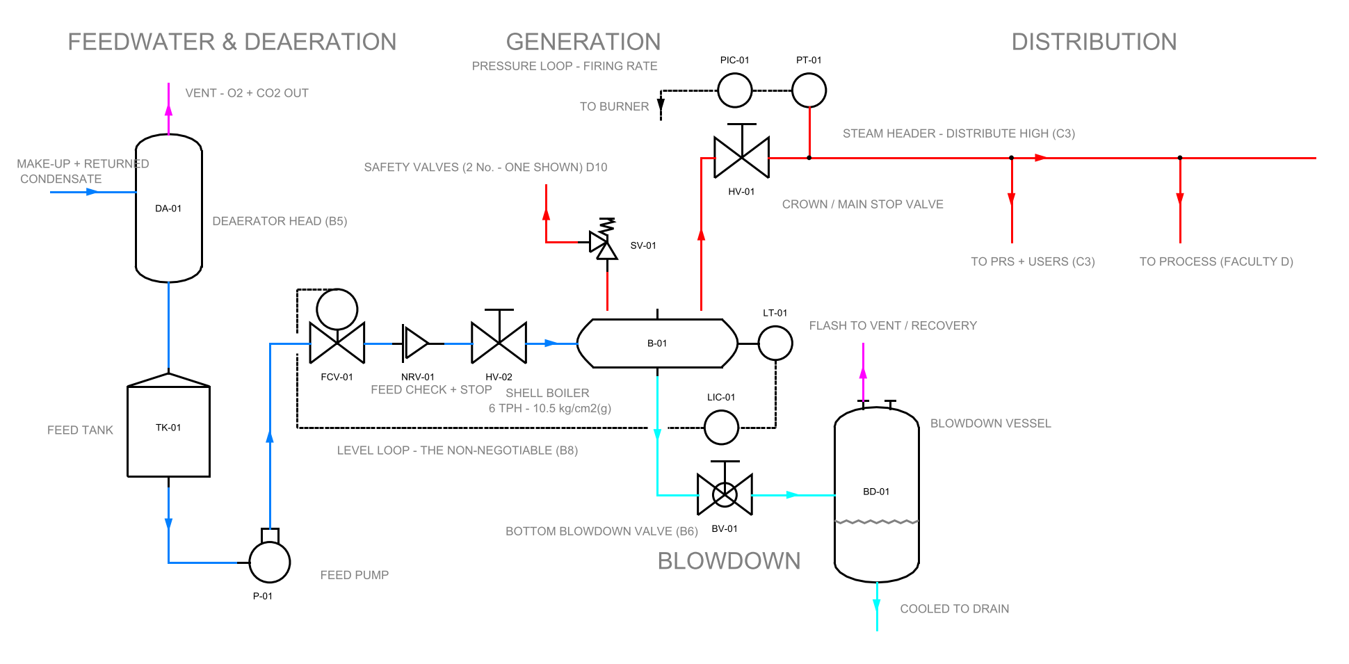
The safety chain: assume the loops fail
Controls keep the boiler comfortable; the safety chain assumes they haven't. Its logic is layered, each layer independent of the last: two gauge glasses (or glass plus probes) so level truth never rests on one instrument · two independent low-water cutouts that kill the fire on falling level — first-low alarms, second-low locks out through a separate probe and relay · pressure switches above the operating band to stop firing · two safety valves, set at or below design pressure, sized to discharge the boiler's full evaporation with the fire at maximum — the final authority, answering to physics alone (their sizing and terminology get lesson D10) · flame failure on burner plant: lose the flame signal and the fuel valve slams inside seconds, followed by a timed purge before any relight — unburnt fuel in a hot furnace is the explosion nobody gets to learn from · plus interlocks that tie it together: no fan proving, no fuel; purge not complete, no ignition; cutout tripped, manual reset only, by a human who must visit the boiler and look.
Tests that keep the chain honest
A safety device that is never tested is a decoration. The working rhythm: daily — blow down each gauge glass and watch the water return smartly (a sluggish glass is lying); test the low-water alarm via the evaporation or probe-test routine. Weekly — prove the second cutout and the burner lockout. Per schedule — ease each safety valve by hand lever to confirm it lifts free and reseats. Annually — the IBR inspection (lesson B10): hydro test, internals opened, records signed. Log every test; the logbook is both the legal record and the earliest detector of drift.
- Watch one full firing cycle on shift: pressure band, level response, flame pattern. Most control faults are visible before they are audible.
- Gauge-glass blowdown is the highest-value ten seconds in the boiler house — a choked glass reading "normal" precedes most low-water incidents.
- Never wire around a tripped cutout to "get through the shift". The trip is the system working; the bypass is the accident report's first line.
- Safety valves: no gags, no added washers, no "adjusting" by maintenance. Set pressure belongs to the certified workshop and the inspector.
- Three loops run the boiler: level (non-negotiable), pressure→firing, combustion air. O₂ trim is the one that pays rent.
- The safety chain assumes the loops fail: duplicated level truth, duplicated cutouts, two safety valves, flame failure, interlocks.
- Swell fools simple level control on hard load pickups — two-element control exists for that moment.
- Untested protection is decoration: glass daily, cutouts weekly, SVs eased on schedule, everything logged.
The humble fusible plug tells the whole philosophy in one fitting: a bronze plug in the furnace crown, cored with tin, submerged in water. Lose the water and the tin — no longer cooled — melts at its set temperature, and the escaping steam douses the fire and announces the emergency with a scream no operator can ignore. A safety device with no electronics, no power supply and no way to be bypassed quietly: nineteenth-century engineering stating, in cast metal, that the last line of defence must not depend on anyone remembering to test it.
FAQ
Why does drum level briefly rise when a big load switches on?
That is "swell": the sudden demand pulls pressure down, the steam bubbles below the water surface puff up, and the level gauge reads higher even though the boiler holds less water. A naive controller sees "high level" and cuts feed — exactly the wrong move. Two-element control (level plus steam flow) exists for that moment; on fast-swinging water-tube plant it is not a luxury.
How often should the gauge glasses and cutouts actually be tested?
Glasses: blow down daily and watch the water return smartly — a sluggish glass is lying, and a choked glass reading "normal" precedes most low-water incidents. Low-water cutouts: alarm routine daily, the second (lockout) cutout proved weekly. Safety valves: eased by hand lever on schedule. The IBR inspection closes the loop annually (B10). Log every test — the logbook is the legal record and the earliest drift detector.
The low-water cutout tripped and production is waiting. Can we bridge it for the shift?
No — and this is the one "no" in the boiler house with no exceptions. The trip is the system working; the bypass is the first line of the accident report. The design already says so: a tripped second cutout demands manual reset by a person who must walk to the boiler and look. Find the level problem; the shift can wait.
Why two gauge glasses, two cutouts, two safety valves — isn't one enough?
Because the safety chain is built on the assumption that any single device fails. Level truth never rests on one instrument; the second cutout works through a separate probe and relay so no single fault silences both; and the two safety valves are the final authority, answering to physics alone. Redundancy here is not caution — it is the design method.
Why must a burner purge before every relight?
Because unburnt fuel in a hot furnace is the explosion nobody gets to learn from. On flame failure the fuel valve slams within seconds, and the timed purge then sweeps any fuel-air mixture out of the furnace before ignition is even permitted — the interlock reads: purge not complete, no ignition. The seconds it costs are the cheapest insurance on the plant.
Check yourself
Five quick questions on this lesson. No marks, no records — the score is for you.