
Lesson A8 left a question hanging: what do you do with flash steam when there is no low-pressure user to give it to? The industrial answer is a machine with no motor, no rotor and no seals to speak of — a steam-jet thermocompressor, which uses a little high-pressure steam to drag low-pressure steam back up to a useful pressure. This deep-dive explains how it works, and then examines the one design choice that decides whether an installation keeps performing when the plant's load moves: the choice between a fixed nozzle and a variable (spindle-controlled) nozzle. It is a 300° lesson: we will name products, cite manufacturers' published literature, and state exactly what is proven and what is not.
How a steam jet compresses steam
Three phases, one thermodynamic cycle:
- Expansion. Motive steam enters a converging–diverging nozzle, reaches the speed of sound at the throat (the choked-flow physics from the leak-cost lesson — here put to work), and leaves the diverging section at several times the speed of sound. Pressure energy has become a supersonic jet.
- Entrainment. The jet's low-pressure wake draws in the suction steam — your flash — and drags it up to speed in the mixing section, transferring momentum kilogram by kilogram.
- Compression. The mixed stream decelerates through a diffuser; a train of shock waves converts velocity back into pressure, delivering the whole flow — motive plus suction — at the discharge pressure, ready for the header.
Two ratios describe every duty: the compression ratio K = Pd ÷ Ps (absolute), and the entrainment ratio — kilograms of suction steam carried per kilogram of motive. Every kilogram entrained is a kilogram the boiler does not raise.
The threshold that rules the machine: K ≈ 1.8
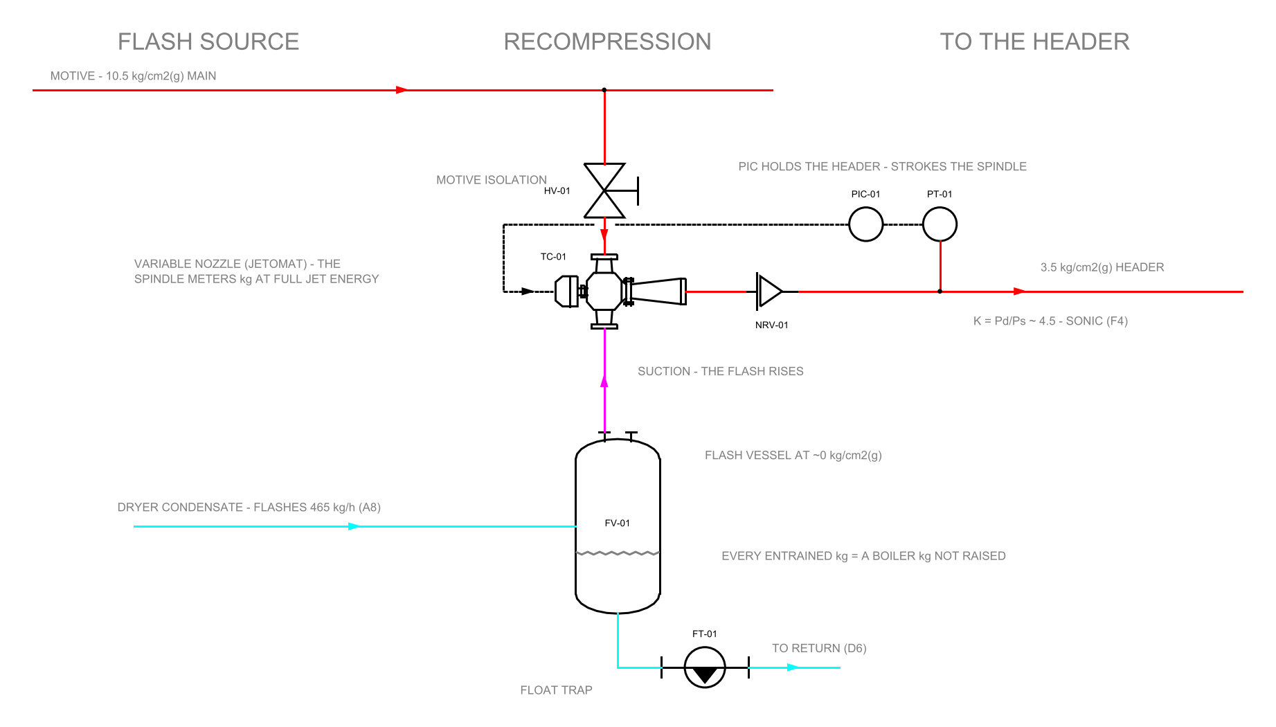
Above a compression ratio of about 1.8:1, the flow in the diffuser throat itself goes sonic and the machine operates in critical mode. This threshold is not a marketing figure — it is published, as the same number, by two independent ejector manufacturers (Croll Reynolds; Transvac). In critical mode the motive flow is locked by nozzle geometry and motive pressure — and most real recovery duties, such as lifting atmospheric flash into a 3.5 kg/cm²g header (K ≈ 4.5), are deeply critical.
Critical mode also has a cliff. The shock system standing in the diffuser can only hold so much back-pressure: push beyond it — or weaken the jet — and the shocks are expelled, entrainment collapses, and the unit breaks: suction pressure spikes and recovery stops. Worse, the recovery is not symmetric: ejector literature documents the hysteresis — after a break, conditions must be restored beyond the failure point before the machine picks up load again. On a running plant that means venting steam or operator intervention after every upset.
The fixed nozzle: a single-point machine
A fixed-nozzle thermocompressor is three stationary parts — nozzle, mixing section, diffuser — with no moving element at all. Its virtue is genuine: simplicity, low price, nothing to maintain. Its constraint follows from the choked-flow law: fixed throat + fixed motive pressure = fixed motive consumption. The makers state it themselves: Croll Reynolds — optimal efficiency "at a single set of suction, discharge and motive pressure conditions"; Schutte & Koerting — fixed-nozzle compressors are for "a steady load"; Spirax Sarco's technical information for its fixed-orifice SJT puts suitability at roughly ±10% around the design point.
Away from that point, the behaviour is documented in the same makers' literature:
- Falling load: the machine still swallows full motive steam whether or not there is flash to entrain — high-value steam spent on nothing, or the suction vessel pulled needlessly deep.
- Throttling the motive (the only external handle) destroys the very pressure energy the nozzle exists to convert; the jet weakens and the margin to the break point shrinks. Above the 1.8 threshold, Spirax's own document rules its motive-control options out entirely for sonic operation.
- Off-design pressure: Croll Reynolds' published figures for a 100 psig-design nozzle: 21.7% less steam at 75 psig — and +43.5% consumption at 150 psig. Boilers sag rather than surge, so a fixed unit spends much of its life on the weak side of its design point.
- The published workarounds concede the point: banks of parallel fixed units switched in steps (Transvac; S&K), or venting the surplus. A bank steps; a load moves.
None of this is a criticism of fixed-nozzle machines on genuinely steady duties. A continuous, single-product, flat-load process is exactly where the simpler machine is the better engineering — and an honest offer says so in writing.
The variable nozzle: making the restriction the control element
The variable-nozzle machine — supplied in India as the Jetomat, the Bälz 590 controllable-nozzle steam ejector, engineered and supported by i-Kcal as Bälz's Indian partner — puts a precision-tapered spindle inside the nozzle throat. An external actuator strokes the spindle; the throat area follows; the choked-flow law turns from a lock into a control handle:
- Kilograms change, energy per kilogram does not. The motive line stays at full pressure at every load; the spindle meters how many kilograms pass. Each kilogram still expands from full line pressure to full jet velocity — the jet gets smaller, not weaker.
- The shock system stays home. Closing the throat at low load keeps the nozzle-to-diffuser area ratio matched to the flow — precisely the condition that holds the machine inside its stable regime, where a throttled fixed unit drifts toward its break point.
- To the control system it is just a valve. Positioner, 4–20 mA setpoint, continuous modulation on discharge pressure, suction pressure or flow — no anti-break floor logic, no step transitions, no reset procedure after upsets.
Turndown: the number nobody publishes
Here the honest reporting matters. A survey of the steam-ejector industry's published literature (August 2026) finds no manufacturer publishing a motive-nozzle turndown figure. (A "100% to 0%" figure sometimes quoted is suction-side turndown — a different quantity.) What the i-Kcal delivered record documents — factory documents and running installations — is up to 10:1 motive turndown on a single DN80 body:
- a factory-measured cone-contour curve for one delivered DN80 machine, metering motive steam continuously from 26 to 3,010 kg/h across a 40 mm spindle stroke — 41 measured points at constant motive pressure;
- maker's selector verification of the same duty at both 300 and 3,000 kg/h motive on a DN80 at identical pressures, with healthy entrainment at both ends;
- delivered machines running today: a DN80 modulating 500–2,500 kg/h (5:1) on a plywood-press duty; a DN65 modulating 400–1,500 kg/h (3.75:1) on a corrugator line;
- third-party corroboration: a Gujarat agrochemical plant's public CII National Energy Award submission (2019) records that a fixed-nozzle thermocompressor could not be used for its intermittent flash duty, and reports 422 kg/h recovered with a variable-nozzle machine.
And the limit of the claim, stated plainly: these are selection and factory-test figures, not site measurements of turndown-in-service — which is why current projects build in motive and suction flow metering, so the recovery is proven in operation, not on paper.
One duty, across its load range
| Load | Fixed nozzle | Variable nozzle |
|---|---|---|
| 100% | Peak efficiency — this is the point it was bought for | Peak efficiency — spindle at design position. Parity. |
| 75% | Motive throttled; jet weakens; break-point margin shrinks | Spindle closes; full pressure kept; entrainment healthy on less steam |
| 50% | On high-lift duties, typically venting / bypassing / on-off to stay online | Continuous modulation; shock system held; recovery continues |
| ~10% | Effectively offline — full motive spent doing nothing, or bypassed | Still metering — the delivered DN80's factory curve reaches 26 kg/h |
Five questions to put to any thermocompressor offer
- 1. What is my duty's compression ratio, and is the unit sonic there? Pd ÷ Ps in absolute. Above ~1.8, a fixed nozzle's motive flow is locked.
- 2. If it is sonic, how exactly is capacity controlled when my load changes? Motive throttling is not an answer above the threshold — the makers' own literature says so. On/off, venting or a stepped bank are the honest fixed-nozzle answers; ask which is proposed and what it costs in steam.
- 3. What happens when my motive pressure sags below design? It will — busy plants sag. For a fixed orifice: less flow AND less energy per kilogram, sliding toward the break point. Ask for the compensation mechanism.
- 4. Show me the motive-side turndown curve of the actual machine. A factory-measured stroke-versus-flow curve — not a suction-side percentage. If none exists, the machine has one design point.
- 5. How will the promised recovery be verified after commissioning? Metering — motive and suction — reported against the sizing. Insist on it, from every vendor, including this one.
- A thermocompressor upgrades flash with motive steam: expansion → entrainment → recompression, no moving machinery in the flow path.
- K = Pd/Ps absolute. Above ≈1.8 (published: Croll Reynolds, Transvac) the machine is sonic: fixed motive flow, hard break point, hysteresis.
- Fixed nozzle = right for genuinely steady loads. Moving loads: it wastes motive, steps, vents, or drops out — per its own makers' literature.
- A spindle in the throat meters kilograms at full jet energy: delivered record up to 10:1 motive turndown on a single DN80 body.
- Selection is a statement about your load profile. Measure the load first; demand the factory curve; meter the result.
This lesson condenses an i-Kcal technical white paper that develops the physics, the manufacturers' published data and the delivered record in full, with references — available to customers on request via i-kcal.com. Published sources cited above: Croll Reynolds thermocompressor bulletin; Transvac thermocompressor pages; Schutte & Koerting Bulletin 4F and performance papers; Spirax Sarco TI for the fixed-orifice SJT; the 2019 CII National Energy Award submission of the plant concerned.
The ejector's family tree starts in 1858 with Henri Giffard — balloonist, engineer — who needed to feed water into a locomotive boiler against the boiler's own pressure without a pump. His "injector" used the boiler's steam to throw feedwater into the boiler that made the steam — a machine so counter-intuitive that engineers initially refused to believe it worked. It worked on every steam locomotive built for the next century, and its grandchildren are compressing steam in your plant today.
FAQ
How can steam compress steam without any moving machinery?
By trading pressure for velocity and back again. Motive steam expands through a converging–diverging nozzle to several times the speed of sound, the supersonic jet entrains the low-pressure suction steam and gives it momentum kilogram by kilogram, and the diffuser's shock train converts that velocity back into pressure. The only thing that "moves" in the flow path is the steam itself.
What is the difference between compression ratio and entrainment ratio?
Compression ratio K = discharge ÷ suction pressure, both absolute — it describes how hard the duty is. Entrainment ratio = kilograms of suction steam carried per kilogram of motive — it describes what the recovery earns, because every entrained kilogram is one the boiler does not raise. Quote both when you specify a duty.
Why can't I just throttle the motive steam to control capacity?
Above the K ≈ 1.8 threshold the machine is sonic: throttling destroys the very pressure energy the nozzle exists to convert, so the jet weakens and the margin to the break point shrinks. The manufacturers' own literature rules motive throttling out for sonic operation — the honest fixed-nozzle answers are on/off, venting or a stepped bank of units.
What does it mean when a thermocompressor "breaks"?
The shock system in the diffuser can only hold so much back-pressure. Exceed it — or weaken the jet — and the shocks are expelled: entrainment collapses and suction pressure spikes. Recovery is hysteretic: conditions must be restored beyond the failure point before the machine picks up load again, which on a running plant means vented steam or operator intervention after every upset.
Is a fixed-nozzle thermocompressor ever the right choice?
Yes — on a genuinely steady, flat-load, single-product duty it is the better engineering: three stationary parts, low price, nothing to maintain. The machine only disappoints when the load moves, because a fixed throat at fixed motive pressure means fixed motive consumption regardless of how much flash there is to recover. An honest offer states which case yours is, in writing.
Check yourself
Five quick questions on this lesson. No marks, no records — the score is for you.